A Basic Guide to Tooling Design
The discipline of tooling design is fundamental to manufacturing. The cost of manufacturing and of the end product depends heavily upon tool design.
Tool design affects cost in several ways. First, it determines the tool life, which is how long the tool last before requiring a replacement. Second, it affects the quality of the product, and any cost of poor quality and rework costs, which adds into the total cost of the final product. Third, tool design can affect the cycle time a manufacturing process, which enables us to produce more or less units in a given time. For these reasons, it is important to understand the fundamentals of tool design.
This article will cover various basic aspects of tooling design, including the different types of tools, their KPIs (key performance measures), their properties, and factors to consider when designing a tool.
Definition
Tooling design is a specialized area of manufacturing engineering which comprises the analysis, planning, design, construction and application of tools, methods and procedures necessary to increase manufacturing productivity. [Dr. Nageswara Rao Posinasetti]
Objectives of Tooling Design
1. Manufacture a product within the acceptable limits at the lowest possible cost. (Keep in mind that the overall cost of production is highly influenced by the cost of tooling.)
2. Increase production by designing tools that have faster production rates.
3. Maintain the quality of the end-product by designing tools which consistently produce good parts.
4. Design tools that are easy and safe to use and operate.
Types of Tools
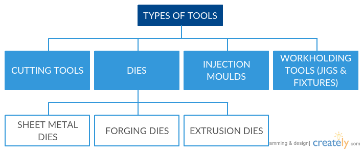
Cutting tools
Machining processes require cutting tools that undergo huge forces and experience significant temperature gradients. In general, there are four aspects of cutting tools that must be considered:
Tool Life: This is the life of the tool, beyond which it loses its operational characteristics. There are two broad categories of tool failures:
- Premature failure: Fracture failure from excessive cutting forces, or Thermal failure from high cutting temperatures
- Gradual failure: A cutting tool will gradually fail as it approaches its life-limit with operational use.
Tool Materials: There are some tool material properties that must be considered:
- Toughness: The tool’s ability to avoid fracture
- Hot hardness: The hardness of a material at high temperatures
- Wear resistance: The tool’s ability to resist abrasion
Tool Geometry: Each tool is described by its geometry and angles. Every tool shape has a specific purpose in metal-cutting intended to achieve the most efficient separation of chips from the work-piece. This is what makes tool geometry important.
Cutting Fluids: The use of cutting fluids is extremely important in cutting operations. The following are the few important aspects of cutting fluids:
- Tooling: Reduction of heat generated in the friction and shear zone.
- Lubrication: Reduction of friction between tool and chip.
| Chemical formulation | Application methods | ||
| Cutting oils | Cooling effect increases downwards | Flooding | Lubrication effect decreases downwards |
| Emulsified oil | Mist | ||
| Chemical fluids | Manua | ||
Sheet Metal Dies: The word “die” is used to describe the tooling used to produce stamped or formed parts. A die set consists of a male and a female component which work in opposition to each other. The upper half of the assembly, which may either be the male or female, is mounted on the press ram which then delivers the stroke action.A die is a specialized tool used in manufacturing to cut and/or shape material using press-working machines. Dies have many forms and they can be classified as follows:
| Sheet Metal Processes | |
|---|---|
| Blanking | Blanking is a shearing process in which a flat piece of material is produced by cutting a desired shape in one single operation. |
| Perforating | Perforating is a piercing operation in which a large number of holes are punched together. |
| Notching | Notching is also a piercing operation that removes the edges of a work-piece. |
| Shaving | Shaving is a shearing process in which a small amount of an already blanked part is removed. |
| Trimming | Trimming is used as final operation in which excess and unwanted irregular material is sheared off from drawn sheets. |
| Cut-off | Cut-off process is used to separate a stamping from a stock/strip. |
Forging Dies: Forging is a manufacturing process that shapes metal using localized compressive forces. Forging can be classified according to the temperature of the process:
i. Cold forging
ii. Warm forging
iii. Hot forging
For warm and hot forging the work-piece is heated prior to the press-working operation.
Extrusion Dies: Extrusion is a process that is used to create a cross-sectional profile using a die tool. The material to be extruded is pushed through the die tool. Such a process has two major advantages. First, very complex geometries can be achieved. Second, brittle materials can be formed only compressive and shear forces are applied (brittle materials are sensitive to tensile forces). Just like forging, extrusion can also classified according to the temperature at which the process is performed. The classification is as follows:
i. Cold Extrusion
ii. Warm Extrusion
iii. Hot Extrusion
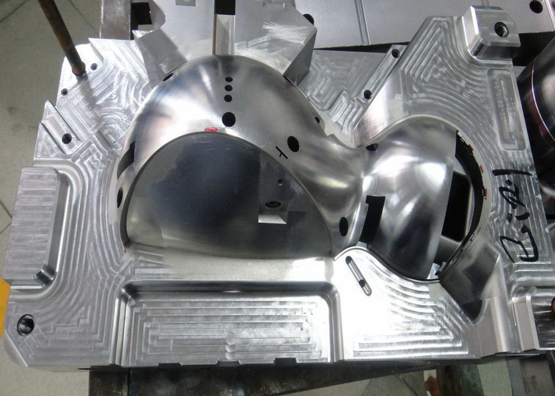
Injection Mould Tools
Injection molding is a manufacturing process in which parts are produced by injecting molten material into a mold. Injection molding can be performed using a variety of materials including metals (the process for metals is called die-casting), glass, thermosetting and thermoplastic polymers.
Work-Holding Tools
Work-holding tools include any device that is used to hold the work-piece in place for the cutting tool. This can include clamps, vices, chucks, fixtures, etc. The decision as to how to hold a work-piece may depend on the following:
- which surfaces can be machined in a single-setup
- machining process accuracy
- cutting forces, speed and feed-rate
- tool-path
- tool-size and shape
Tool Materials
The physical properties of a material control how the material reacts under certain conditions. Physical properties are natural to a material and cannot be permanently be altered without changing the composition of the material itself. These physical properties include:
- Density: The material’s weight per unit volume, such as; lb/ft3 or kg/m3.
- Color: The natural tint of the material.
- Electrical Conductivity: The measure of a material’s ability to permit the flow of electric current.
- Thermal Conductivity: The function of how fast heat can flow through a material.
- Thermal Expansion: The measure of the dimensional change exhibited by the material when exposed to heat, thus affecting accuracy.
- Melting Point: The temperature at which the material changes from the solid to the liquid state. It can also be defined as a rough measure of heat resistance.
Cutting Tool Design
Cutting tool design requires an understanding of the machining process, the materials involved, and the operation parameters. The following should be considered:
- Setup rigidity: A rigid setup is vital to achieve accuracy and surface finish. Both the work-piece and the cutting tool must be rigid to control vibrations and chatter during machining. Increasing the mass of machining system elements promotes rigidity by reducing vibrations and resonant frequency.
- Cutting tool strength: Cutting tools must be strong enough to prevent breakage and deformation by the machining forces. They should also be designed to overcome overload situation that maybe encountered during intended work-life.
- Weak links: Weak links such as wear and break-away members are commonly considered for the possibility of tool failure. This limits the damage to indexable insert cutting tool-holders and machine tools.
- Force limitations: Operating forces obviously maybe limited by the above-mentioned weak links.
- Speed, feed & size: A machine tool’s speed and feed ranges, adapter capacity and working clearances are all established restrictions on tool design and production rates.
Fixture Design
Fixtures range from standard clamps to vices and chucks to metal plates with key-slots and tap-holes for fasteners. They can also be part-specific dedicated fixtures requiring extensive design and build requirements. To correctly machine a part, it must be held in a setup that guarantees a definite location with respect to the part’s datum points and surfaces. This must be repeatable for many parts.
The fixture must also hold the part securely while vibrations, cutting forces, centrifugal forces and gravity act to dislodge the part. In theory, the location and clamping of work-pieces are considered separate issues, but locating and clamping are integral; once located, the holding action must ensure the work-piece is stable for machining. Conversely, the clamping force should not be so excessive such that it distorts, gouges, or breaks the work-piece.
Computer Aided Design (CAD)
Computer-aided design (CAD) is of immense importance when it comes to tool design and manufacturing.
CAD is the use of computer systems to aid in the creation, modification, analysis, or optimization of a design” [Narayan, K. Lalit]
The use of CAD platforms has increased designers’ productivity, improved design quality and eased communication among various disciplines. CAD output is often in the form of electronic print and machining data (program/operation code). Tool designers utilize CAD in the same way as product designers, creating 3D models, 2D prints, and machine code to produce all types of tooling.