Ball Bearings: Guide to Selection, Applications & Calculations
This article helps mechanical engineers understand the selection of ball bearings depending upon the application and load conditions. Primarily the article helps you calculate the minimum and maximum load bearing capacity of bearing and most importantly… life of the bearing as an individual. Here the designation number of the ball bearing helps you know the design, working nature and the physical property of the bearings.
In this new edition, I have come up with accuracy, operating temperatures, re-lubrication features along with applications, utility and system of operations recommended by American Society of Mechanical Engineers (ASME). You can also observe reflections of rules abiding ANSI/API standards putting a significant relevance with bearing operations from maintenance point of view.
Introduction
For Pumps used in Petroleum Industries and Gas Industries, we have some standard statements meant to be followed:-
Each Shaft shall be supported by two radial bearings and one double acting Thrust Bearing which may or may not be combined with one of the radial bearings. This means, The thrust bearing may or may not be in the same axis as the rest of the two radial bearings. In other words, it can also said as, the thrust bearing can be arranged in such an order that, it may or may not be a part of the system bearing calculation although supporting the shaft.
Here, there can be only three possible system of arrangements,
- Rolling Element radial and Thrust.
- Hydrodynamic radial and rolling element thrust.
- Hydrodynamic radial and thrust.
Deep Groove Ball Bearings
Application: Deep Groove Bearings are used for small diameters with radial and axial loads.
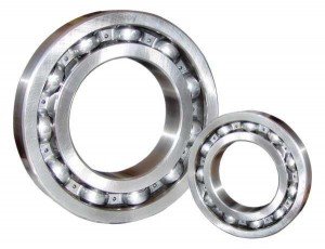 Bearings I.D: For any designated no. in any bearing company, the bearing I.D. is equal to 5 times the last two digits.
For example,
6208 = I.D. 40mm
2313 = I.D. 65mm
But things change when suffixes are added beyond the designation no. of the bearings.
Example:- 626z – here, 6mm is the I.D. and 6 mm is the thickness, with single shield.
627-2z – here, 7mm is the I.D. and 7 mm is the thickness, with double shield.
NOTE: For the selection of the bearing, ‘C’ is important. If it is equivalent to C/P x Fr, in terms of Newtons, then bearing matching the load bearing capacity will be suitable.
NOTE: For the selection of the bearing, ‘C’ is important. If it is equivalent to C/P x Fr, in terms of Newtons, then bearing matching the load bearing capacity will be suitable.
Supplementry Designations:
- K – Roller and Cage assembly of a cylindrical roller thrust bearing. Example:- KNU07.
- L – Removable inner and outer ring of a separate ring. Example – LNU207.
- R – Separate bearing without removable inner and outer ring.
Suffixes:
A, B, C, D, E – Differed or modified internal design.
External Design:
| Ref | Description |
| X | Boundary dimensions altered to conform to ISO standards. |
| RS and LS | Rubbing seals at one side of the bearing |
| 2RS and 2LS | Rubbing seals at both sides of the bearing |
| Z | Shield (Non-rubbing seals) at one end of the bearing |
| 2Z | Shield (Non-rubbing Seals) at both sides of the bearing |
| K | Tapered Bore, 1:12 on diameter |
| K30 | Tapered bore, 1:30 on diameter |
| N | Snap ring groove in outer ring |
| NR | Snap ring groove in outer ring, with snap ring |
| ZN | Shield at one side of the bearing and snap ring groove in outer ring at other side |
| ZNR | As ZN, with snap ring |
| N2 | Two locating slots in outer ring |
| G | Single row angular contact ball bearing for paired mounting, back to back or face to face bounting |
Cage:
| Ref | Description |
| J | Pressed Steel Cage |
| Y | Pressed Brass Cage |
| M | Machined Brass Cage |
| F | Machined steel or spheroidal graphite cast iron cage |
| L | Machined light alloy cage |
| P | Injection molded cage of glass fibre reinforced plastic |
| TH | Snap type of fabric reinforced phenolic plastic |
| IH | Injection molded cage of plastic |
| V | Full component bearing |
| VH | Full component bearing with non-separable roller component |
Other Bearing Features:
Accuracy:
a. P6 – ISO clearance class 6.
b. P5 – ISO clearance class 5.
c. CLN – ISO clearance of class 6X for taper roller bearings.
Relubrication Feature:
Classification as holes provided in the bearings to lubricate.
a. W 20 – 3 Holes in outer Ring.
b. W 26 – 6 Holes in inner Ring.
c. W 33 – Lubrication Groove and 3 holes in the outer ring.
d. W 33X – Lubrication Groove and 6 holes in the outer ring.
e. W 5/3 – This class has combined features of class W 26 and W 33.
f. W 5/8 – This class has combined features of class W 20 and W 26.
g. Q E5 – Special Electric motor quality, dimensional and running accuracy to P6 for high demands of silent running.
h. Q E6 – Normal Electric motor quality, for quiet running application.
i. Q 05 – Vibration peaks extra low.
j. Q 06 – Vibration peaks lower than normal.
k. Q 5 – Vibration level extra low (supersedes C6).
l. Q 6 – Vibration lower level than normal (supersedes C6).
m. Q 55 – This class has combined features of class Q 5 and Q 05.
n. W 66 – This class has combined features of class Q 6 and Q 06.
Classification as per temperature.
a. MT – Grease for medium temperature. (-30°C to 110°C)
b. LT – Grease for medium temperature. (-50°C to 80°C)
c. HT – Grease for medium temperature. (-20°C to 130°C)
Stabilization Feature:
Bearing rings are dimensionally stabilized for operating temperature.
a. S0 – Up to +150°C
b. S1 – Up to +200°C
c. S3 – Up to +250°C
b. S4 – Up to +300°C
c. S5 – Up to +350°C
Self-Aligning Ball Bearings
Self-aligning ball bearings have two rows of ball bearings and common sphered raceway in the outer ring, permitting minor angular misalignment of the shaft relative to housing. Thus, they are perfect where misalignment arise. These bearings have a tapered bore to automatically permit minor angular misalignments.
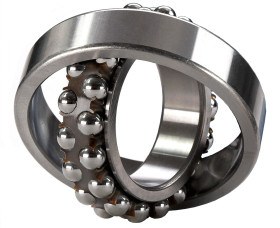
Fig.2 : Self-aligning ball bearings
Angular Contact Ball Bearings
In angular contact bearings, the line of action of the load (load line), at the contacts between balls and raceways forms an angle with the bearing axis. The bearings are therefore particularly suitable for combined loads.
Single row angular contact bearings: These bearings can carry axial loads acting in one direction only. The radial load imposed on the bearing induces an axial force in the bearing which must be counteracted. Consequently, the bearings are normally adjusted against the second bearing.
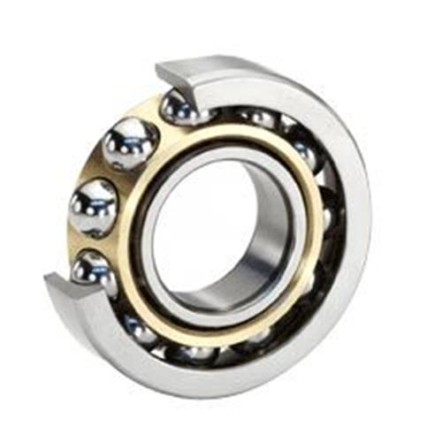
Fig.3: Single row angular contact bearings
Double row angular contact bearings:- These bearings correspond in function to two single row contact bearings arranged back to back. These bearings can also accommodate axial loads in both directions as well as tittling moments, but are narrower.
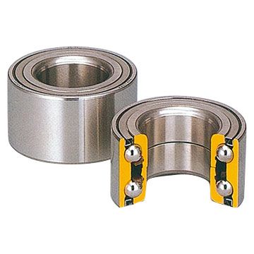
Fig.4: Double row angular contact bearings
Thrust Ball Bearings
Thrust bearings are also called as axial bearings. These bearings are used where high axial loadings are operated under tougher conditions of operations in terms of Temperature, RPM, etc.
In accordance with API 610, the thrust bearings, shall be sized for a continuous operation under all specified conditions, including maximum differential pressures. All loads shall be determined at design internal clearances and also twice design internal clearances. Thrust bearings should provide full-load capacities if the direction of rotation is reversed.
Single Ball bearings: Bearings of this type are suitable for all the accommodation of axial loads in one direction and can locate a shaft in one direction. They must not however be subjected to radial loads.
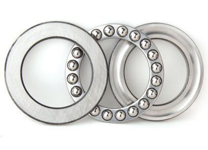
Fig.5: Single ball thrust bearing
Double Ball bearings: This kind of ball bearings can bear axial loads from both sides and thus can be used to locate shaft in both directions. They should not be subjected to radial loads.
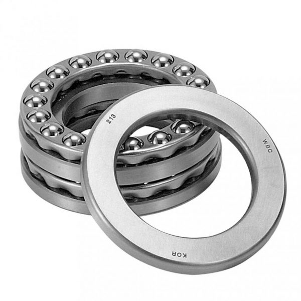
Fig.6: Double ball thrust bearing
Calculations
Calculation of bearing life
The bearing life calculations means, the life of an individual bearing in terms of revolutions that can be utilized under continuous operating conditions designed to specific system operating conditions.
L10 = (106/60n) x (C/P) 3
Where,
L10 = Life of an individual bearing in hours under continuous run.
C = Dynamic load in Newtons
n = No. of Rotations / Minute.
P = Applied Load (effective).
XFr + YFa (3 for ball bearings and 10/3 for roller bearings)
( X = 1 and Y = 0 always).
X and Y are factors required for the calculation of equivalent dynamic bearing load for single and double row deep groove ball bearing, dependent upon axial load (Fa) and radial load (Fr).
Therefore, if Po < Fr, P = Po = Fr.
Po = Axial load and is equal to Po = 0.6Fr + 0.5Fa.
Where, Fr is the radial force and Fa is the Axial Force.
Calculation of maximum permissible axial load in Newtons:
Fap = 3Bd
Where,
B = Bearing Width.
d = Bearing bore diameter.
Fap = Max. Permissible Load.
Calculation of minimum Loads:
The calculation of Minimum Loads in a bearing under operating conditions means to calculation the loads acting over a bearing under static or dynamic conditions.
Fam = A (n/1000)2
Where,
Fam = Minimum Loads in Newtons.
n = No. of Rotations per Minute.
A = Cross-sectional Area of Bore.
Calculation for System Bearing Life:
Let’s understand, what does system bearing life mean. This can be clarified and understood as the criteria that apply to the bearing “system” and not to the individual bearings alone, which should be a general practice in the industry. That means, an individual lige of one bearing may be 100000 Revolutions and the other may juat have 26500 revolutions. But, if the value is put, the system bearing life becomes 25000 Revolutions. This means, a combined effect of life of all the employed bearings in a system should perform atleast 25000 revolutions at continuous run.
As per API Standards, The system bearing life value should be less than the life of any individual bearing having the shortest span of life. The formula for System Bearing Life is:-
L10h = [(1/ L10hA) + (1/ L10hB) + (1/ L10hB) + …….. + (1/ L10hN)]
Where,
L10hA is the basic rating life, L10h, per ISO 281 for bearing A;
L10hB is the basic rating life, L10h, per ISO 281 for bearing B;
L10hN is the basic rating life, L10h, per ISO 281 for bearing N;
N is the number of bearings