What is Creep Strength (Creep Limit)?
A material behaves differently when subjected to an instantaneous high stress or a constant stress for a certain amount of time. When under continuous mechanical stress, a material tends to move gradually or deform in a permanent manner. This natural tendency is called creep. Several factors play in the initiation and progression of creep in a material, including temperature, time, stress, and alloy composition. The rate of deformation due to creep is called creep rate.
It is very important to study creep in various engineering applications, especially those where high temperature and stress are involved. Discs and blades in turbines, spaceship bodies, and steam lines are a few examples of where creep effects may take place [1].
Creep strength, also known as creep limit, is a measurement of a material’s resistance to creep. It is also described as the stress at particular environmental conditions that produces a constant creep rate [2]. In other words, creep strength is the maximum stress endured by a material for a specific period of time without extreme deformation.
Here, you will learn about:
- What creep is and how it naturally occurs
- The 3 stages of creep
- The types of creep deformation
- Creep strength in alloys
- How creep strength is measured
- Design options to minimise creep deformation

What is creep?
Creep is defined as a time-dependent material deformation under continuous stress below the material’s yield strength. It is commonly observed to be quite impactful under elevated temperatures, especially with metals. Yet, it can still take place at room temperature, like with glass and lead, at a much slower rate.
Other names for creep include material creep and cold flow.
When materials are subjected to increasingly high-stress levels over a long period, creep can become severe. This especially applies to materials that are frequently exposed to high heat and can even permanently deform as temperatures reach the melting point. Without exceeding the material’s yield strength, creep can result in plastic strain, which is a unique aspect of this phenomenon, as plastic deformation generally happens when the yield strength is exceeded.
Despite the complexity of its mechanics, creep can be described under 3 consecutive stages, as shown in figure 1.
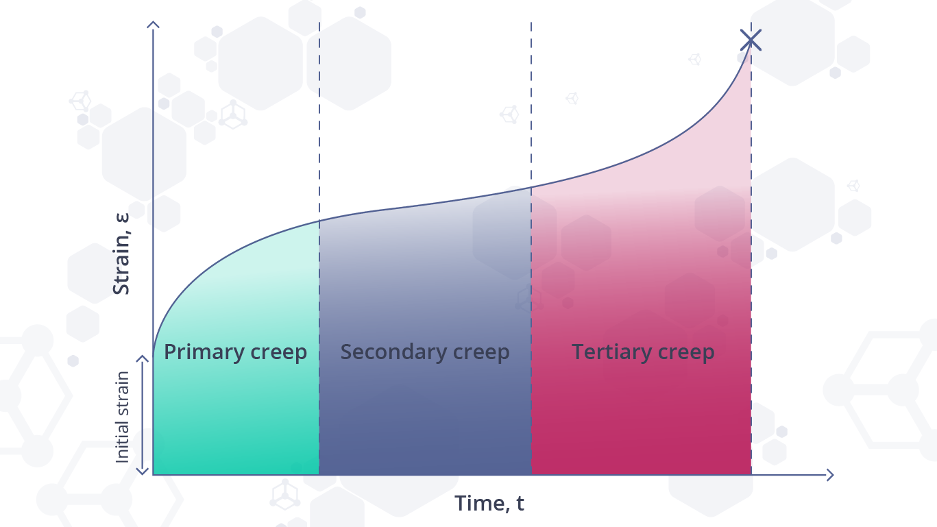
Figure 1: A typical creep curve showing the different stages of creep deformation.
1. Primary Creep
This initial stage is when elastic deformation begins to occur. Afterwards, plastic deformation takes over, as the creep slows down from its initial fast rate due to a process called strain hardening (or work hardening), where the material is strengthened by plastic deformation.
2. Secondary Creep
This stage is also called the steady-state creep. It takes place as the strain rate starts to settle into a constant state. Strain is comparatively slow, as microstructural damage has not been reached yet.
3. Tertiary Creep
This is the final stage in a material’s creep deformation, where deterioration in the material’s microstructure comes about. This continuous damage causes the strain to pick up speed and worsen until sufficient voids in the microstructure are generated, resulting in the material failing in a fracture.
Types of creep deformation
There are various types of creep deformation, including dislocation creep, diffusion creep (bulk diffusion or grain boundary diffusion), dislocation climb-glide creep, and thermally activated glide creep. All these different creep mechanisms depend on the temperature at which deformation is happening, the stress level experienced by the material, and the material’s microstructure and composition. The effect of temperature and stress can be observed in figure 2.
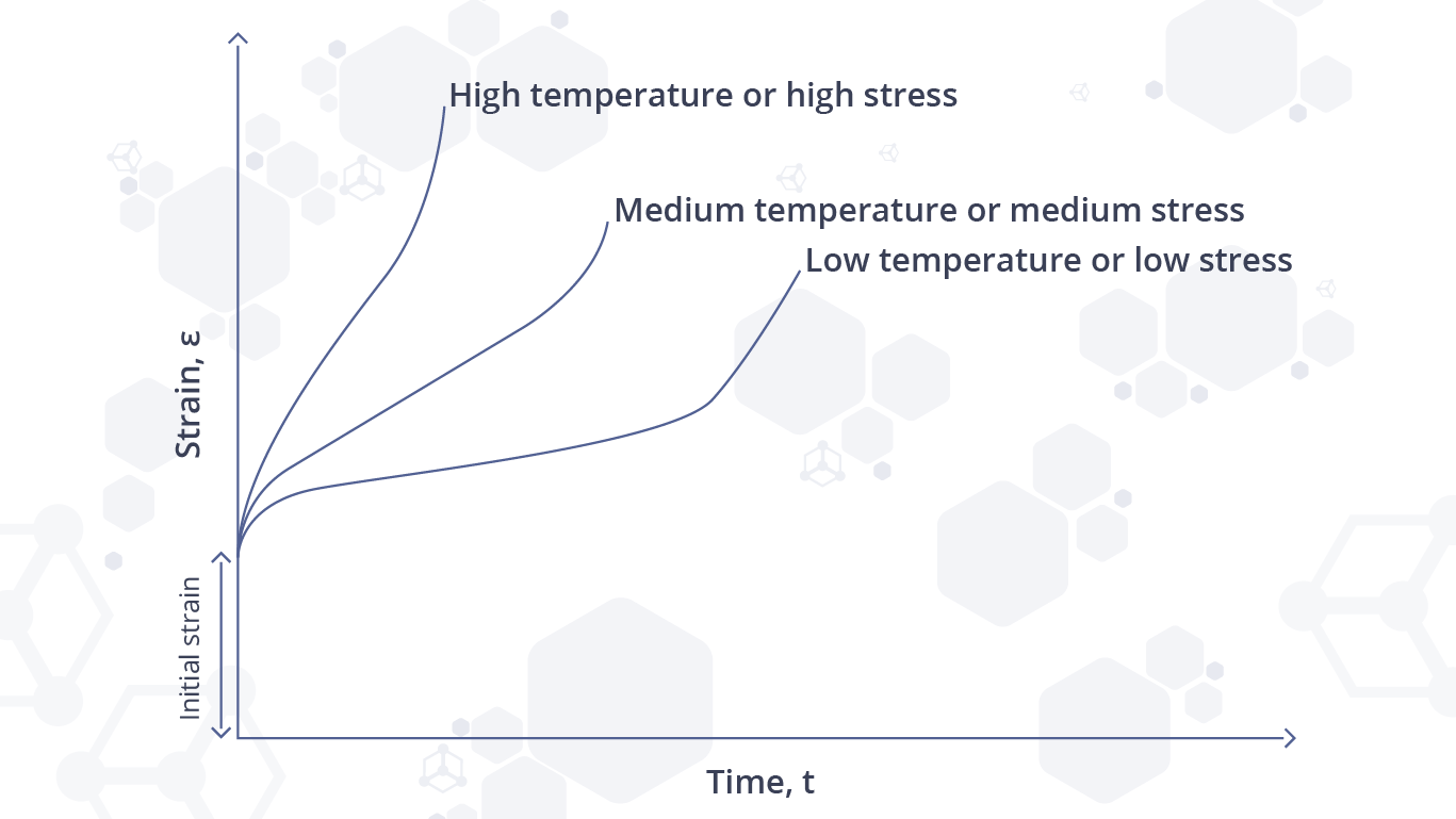
Figure 2: A graph showing the effects of temperature and stress on creep deformation.
On a railway track, for instance, continuously welded rail heated in direct sunshine can buckle. This is caused by increasing stress in the steel and the resultant creep. Concrete may crack under moderate levels of creep, but sometimes this is desirable as it can reduce tensile stresses in the structure. Polymers, when exposed to constant stress, undergo a time-dependent strain growth, commonly known as viscoelastic creep.
Creep strength in alloys
Creep strength is commonly used together with rupture strength, which is the stress at which rupture is produced under certain environmental conditions and for a specified period of time [2]. Being essentially a measure of a material’s resistance to creep deformation, creep strength is deduced from the material’s ability to resist microstructural dislocation movement. That’s why it is also referred to as creep resistance or creep limit. In steels, for example, creep strength becomes significant only at high temperatures. Alloys, particularly aluminium alloys, are prone to creep-fatigue and fracture, due to their low melting point. However, there are other factors that affect the creep strength of alloys, as follows:
Substructure composition
A stable substructure that has uniform dislocations provides resistance to creep-fatigue. However, a substructure that coarsens under strain will result in reduced creep strength. Nickel-based alloys are a good example of this phenomenon. A fine grain size within the structure can also increase creep strength, and vice versa, as smaller grain sizes are coupled with stronger material properties.
Heat treatment
Heat treatment leads to the creation of austenites. Some of these, such as bainite, help to increase creep strength.
Solid solution strengthening
It lessens movement and deformation through the lattice structure, e.g. molybdenum increases creep strength significantly.
Hard precipitate quantity and dispersion
Carbides and intermetallics such as VC (Vanadium Carbide), when dispersed finely and evenly in an alloy, reduce movement and creep.
Therefore, the creep strength inherent in an alloy differs considerably depending on the chemical composition, the spacing of particles in the material, and the treatment or strengthening of the metal.
Here’s a list of materials with their corresponding creep strengths. Note how each has a relative temperature at which creep strength is measured.
|
Material |
Creep Strength Rm (MPa) |
Temperature (ºC) |
Applications |
|
5.6 |
1200 |
Equipment for glass and ceramics industries |
|
|
56 |
700 |
Treatment of radioactive waste, components in boilers and steam generators in pressurised water reactors |
|
|
205 |
600 |
Rays and baskets for heat treatment plants, wire mesh belts in industrial furnaces |
|
|
297 |
500 |
Thermocouple sheathing in aggressive atmospheres, nuclear reactor components |
|
|
385 |
650 |
Bolts, fasteners, turbines, castings |
|
|
440 |
600 |
Equipment for production of super phosphoric acid, offshore industry |
|
|
810 |
550 |
Static and rotating components in aircraft turbines and stationary gas turbines, spacecrafts |
Measurement of creep strength
Creep strength is measured using a creep-testing machine; a device that measures the distortion of a material at various stress levels. It can be used to plot how much stress and strain a material can take, with temperature or loading as variables. The resulting graph will show the 3 distinct stages of creep, primary creep, steady-state creep, and tertiary creep.
The graph can be assessed to pinpoint the temperature and time interval for the various stages of creep. The creep strength or creep limit can thus be ascertained from the tertiary creep stage of the graph.
It is crucial to control the temperature of the chamber within which the creep test is performed in order to keep the effects of thermal expansion minimal.
How to minimise or avoid creep deformation
It is clear now that creep deformation is generally an undesired phenomenon. In order to reduce its effect or prevent it from happening, certain design considerations can be taken into consideration, some of which are:
- Minimise grain boundary sliding by using single crystal materials with large grains and remove microstructural vacancies via adding solid solutions
- Use materials with high melting points
- Minimise diffusivity by using face-centred cubic (FCC) metals rather than body-centred cubic (BCC) metals due to their lower diffusion coefficients
- Use materials with high shear modulus or make use of convenient alloying
- Reduce the working temperature at which the material is utilised (application-specific)
- Refer to creep test data from reliable sources such as Matmatch while selecting materials
Learn more about creep resistance and benefits of creep in this article: "Why Design Engineers Should Consider Creep Resistance of Materials".
Gallery
Sources
[1] V. Monfared, Review on Creep Analysis and Solved Problems, Creep (T. Tanski, M. Sroka, A. Zielinski, ed.s), Intechopen, 2017.
[2] L.W. McKeen, Introduction to Plastics and Elastomers, The Effect of Creep and Other Time Related Factors on Plastics and Elastomers (Second Edition), pp. 1-31, 2009.